Article Overview
For fiber optic connectors, typical insertion loss should be below 0.3 dB for single-mode and below 0.5 dB for multimode, while return loss should exceed 50 dB for single-mode and 20 dB for multimode.
Insertion Loss
Insertion loss (also called attenuation) measures the reduction in optical power as light passes through a fiber optic connector. It is influenced by misalignment, air gaps, and imperfections in the connector components. Lower insertion loss indicates better performance and signal integrity. For standard connectors:
- Single-mode connectors: ≤ 0.3 dB
- Multimode connectors: ≤ 0.5 dB These values are recommended by industry standards and connector manufacturers, and they are critical for maintaining efficient data transmission and minimizing signal degradation over the fiber link .
Return Loss
Return loss (or back reflection) measures the amount of light reflected back toward the source due to refractive index mismatches or surface imperfections. High return loss ensures minimal reflection and better signal quality. Standard reference values are:
- Single-mode connectors: ≥ 50 dB
- Multimode connectors: ≥ 20 dB High return loss is essential for high-speed applications, as low return loss can increase noise and reduce overall system performance .
Standards and Testing
Fiber optic connector loss is governed by standards from organizations such as TIA, IEC, and FOA. Key points include:
- TIA-568.3-D (2022): Specifies transmission performance parameters for multimode and single-mode fibers, including insertion loss limits .
- IEC and TIA testing procedures: Include insertion loss testing, visual inspection, and proper referencing methods to ensure accurate and repeatable results .
- FOA guidelines: Provide field-friendly instructions for testing, avoiding common mistakes, and documenting results for certification . Testing is typically performed using an Optical Loss Test Set (OLTS) or a combination of a light source and optical power meter, following Tier 1 certification procedures for loss, length, and polarity .
Practical Considerations
- Loss budget calculations are essential to ensure the installed fiber supports the intended network application. This includes summing losses from connectors, splices, fiber attenuation, and any passive components .
- High-speed applications (e.g., 10GBASE-SR or 400GBASE-SR4) have stricter insertion loss limits due to shorter allowable distances and higher sensitivity to signal degradation .
- Connector quality and cleaning are critical, as even minor contamination can increase insertion loss and reduce return loss . By adhering to these standards and reference values, fiber optic links can achieve reliable performance, minimize errors, and meet industry compliance requirements.
Link Loss Budget Calculator | Fiber Optic Link Loss Budget
Corning''s link loss budget calculator will calculate your total link loss and tell you if your system falls within Corning''s recommended
Reference to Insertion Loss and Return Loss for Fiber Connectors
As we know, there are a large number of fiber optic cables used between devices in optical communications, and the
Introduction to Optical Fibers, dB, Attenuation and Measurements
This document is a quick reference to some of the formulas and important information related to optical technologies.
E-2000® Connector | High-Performance Fiber Optics | DIAMOND SA
Product Specifications The E-2000® connector family sets the benchmark for mechanical and optical performance. Featuring
Guidelines Corning Recommended Fiber Optic Test
ic system. The components that are entered into the link-loss budget are the fiber optic connectors, fiber splices, and the fiber. The
Determining optical fiber link loss
Fiber loss also varies according to fiber type and performance grade. Most multimode installations are typically 62.5/125-micron fiber,
Reference to Insertion Loss and Return Loss for Fiber
In this comprehensive guide, we will discuss these two parameters, their significance in fiber
QUALITY GRADES OF FIBER OPTIC CONNECTORS
Signal losses in a fiber optic connection When light leaves an optical fiber and enters another one, a little amount of the light is
The FOA Reference For Fiber Optics
In order to test “insertion loss” or the direct loss of a fiber optic cable or cable plant using a light source and power meter (LSPM in
What Is Fiber Loss
FAQ – Fiber Optic Loss What is fiber optic loss? It refers to the optical signal attenuation that occurs as light travels
Understanding Fiber Loss: What Is It and How to
In practical calculation, the actual connector loss can refer to the value in the fiber optic
Connector Loss, Return Loss, and Reflectance – “Highs and Lows”
The condition and characteristics of fiber optic connectors greatly affects the performance of an installed fiber optic
Calculating Fiber Optic Loss Budgets
Don''t use the best possible specs for fiber attenuation or connector loss - give yourself some margin! The best way to illustrate

The FOA Reference For Fiber Optics
In order to establish a typical loss for connectors, it is necessary to test all connectors in a standardized fashion. Measurements of
Fiber Loss Limits – How Much Loss Is Too Much in Fiber Optic Testing?
fiber loss limits explained. Discover what is acceptable loss, how to measure it, and when to take action in fiber optic
What Is Acceptable dB Loss for Fiber Optics?
Learn what dB loss levels are acceptable in fiber optic systems, from connectors and splices to full loss budget
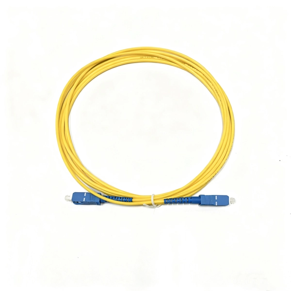
Understanding Losses in Fiber Optic Interconnections
Different fiber optic cables have different specifications on how much the cable can bend without affecting the stated performance or
EAI/TIA 568 B.3 For Fiber Optics
These connection losses are for a fiber terminated in a connector mated to a known good reference connector per FOTP-34 or FOTP
Fiber Optic Cabling Loss Limits Explained – Trend Networks
Learn about fiber optic cabling loss limits & how to calculate them. Gain insights from experts on acceptable loss for
Guidelines On What Loss To Expect When Testing Fiber Optic Cables
Calculating a loss budget for a cable plant involves estimating all the component losses - fiber, splices and connectors - and
Optical Fiber Loss and Attenuation | MEETOPTICS
Fiber loss, also called fiber optic attenuation or attenuation loss, refers to the loss of signal between input
ANSI/TIA-568.3-E: Optical Fiber Cabling and Components Standard
Annexes addressing Optical Fiber Connector Performance Specifications, Grandfathered Fiber and Cable Types and Connecting
Fiber Optic Loss Calculator
Estimate fiber attenuation, connector loss, splice loss, and budget margin for links. Compare wavelengths, distances, safety
Low Loss Connectors and Fiber Outside Diameter
Loss (IL) and Reflection or Return Loss (RL). A superior connector will exhibit minimal optical loss, thanks to precise alignment of th.
LC Fiber Optic Connectors
The fibers shall terminate in 0.049 in. (1.25mm) ceramic ferrules with non-optical disconnect functionality and an average insertion
The Relationship between Insertion Loss and Premium Ferrules
Every fiber connection has two most important values after termination and interconnection - Insertion Loss (IL) and Reflection or
The FOA Reference For Fiber Optics
Optical Fiber Testing - Loss and Attenuation Coefficient For optical fiber, testing includes fiber geometry, attenuation and bandwidth.
Insertion Loss vs Return Loss in Fiber Connectors Explained
Learn what insertion loss and return loss are in fiber connectors, how they are measured, what causes poor